*Please note all of the following content has been approved by the client for public display.
The following project contains 2 phases.
Phase 1:
The client hired me to bring their low fidelity concrete spill alert system prototype to a state where 4 units could be delivered to the customer for a 3 month intensive user testing. This process involved the creation of several deliverables and execution of an onsite installation test.
Deliverable 1.1: Development of a new alarm housing built around the existing electronics for production using SLA Printing. This was to be both a functional and aesthetic development where the client's goal was for the alarm to look as if it belonged in the cab of a concrete truck.
Deliverable 1.2: Production of the client's current sensor housing design using Fusion 360 CAM software and a CNC mill to fit their existing electrical sensor components.
Deliverable 1.3: Development of a branded user manual for the installation and instructions on how to use the alarm system.
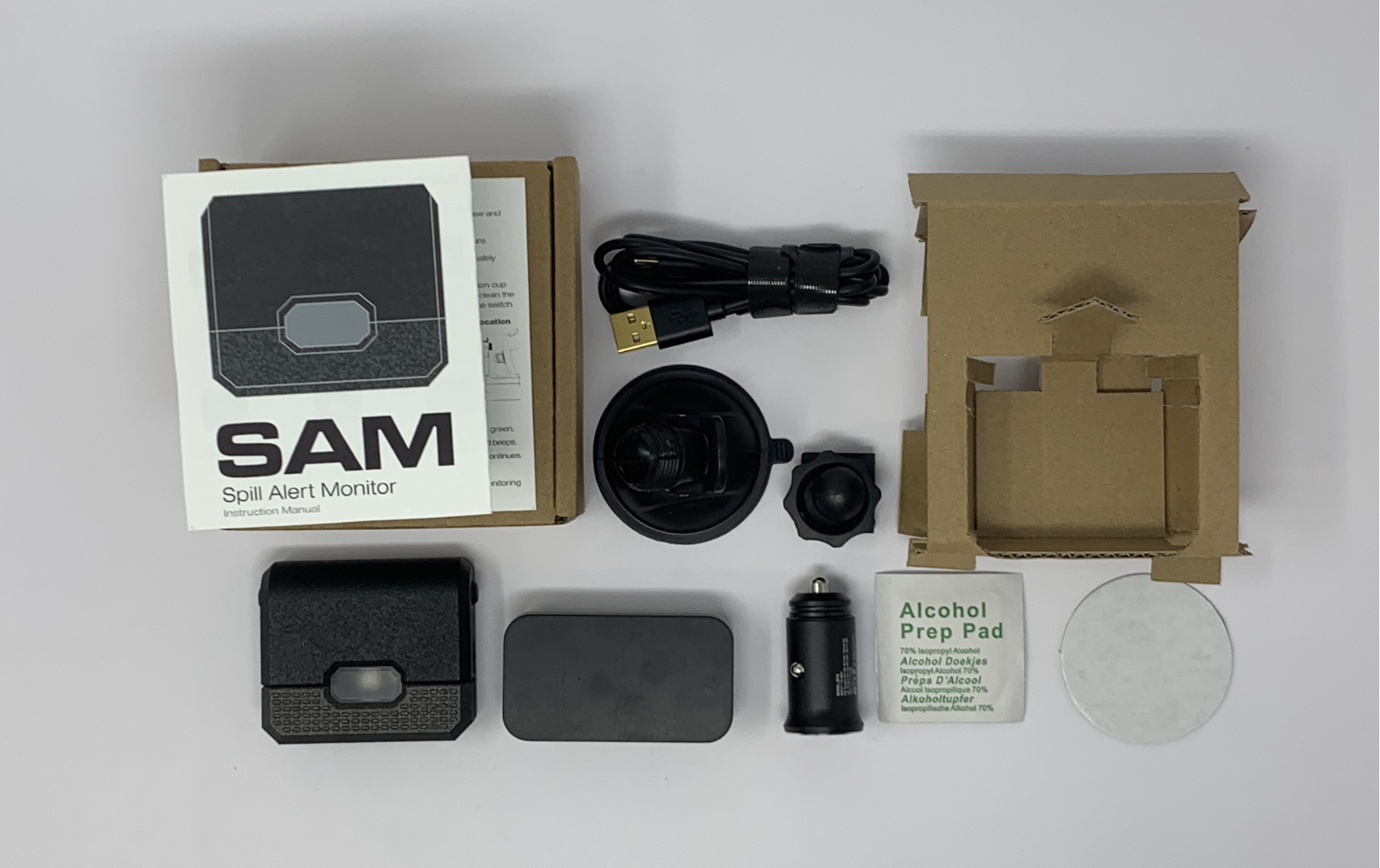
Deliverable 1.4: Custom packaging to house system alarm, system sensor, car charger, charging cable, alarm dashboard stand, alcohol prep pad, and user manual
Onsite Test: To observe the customer's reaction to the new product and ensure the successful installation of the units in/on the concrete trucks for the 3 month user testing period.
New alarm housing development (Deliverable 1.1 )
Prior to the housing redesign, I selected a few images as aesthetic references. The goal was to make the product look like it fit into the concrete truck environment and was targeting products that looked industrial, rugged, and durable.
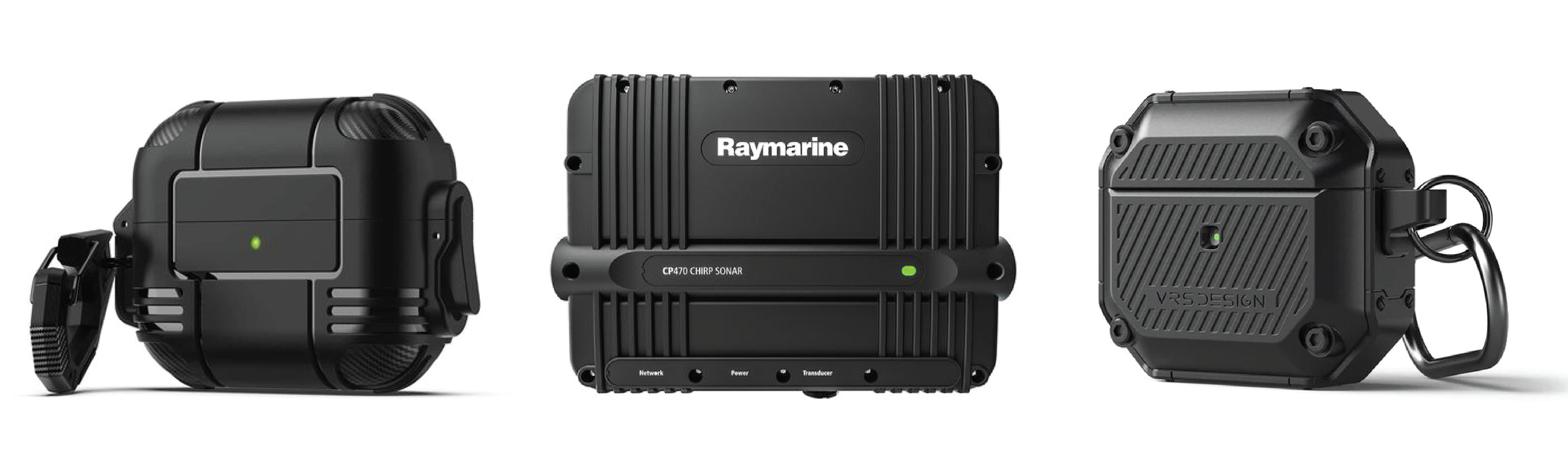
Target form aesthetics: Beveled edges, wide parting lines, and raised simple textures for user touchpoints
Step by step assembly video of the Alarm Unit with the customer's electronic parts. The video has been sped up but the total assembly time is under two minutes. Also, the electronic components have been blurred out as per the customer's request.
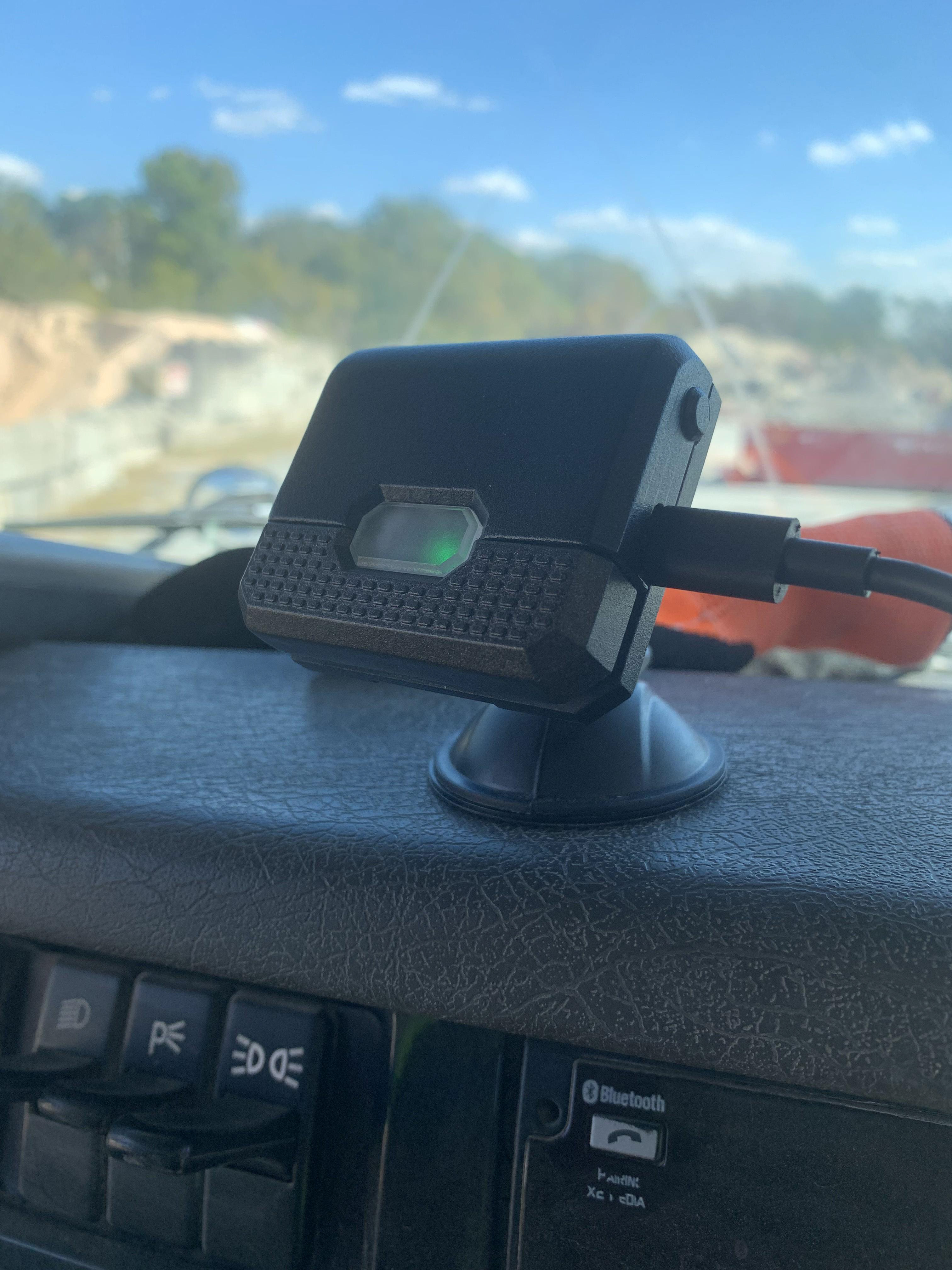
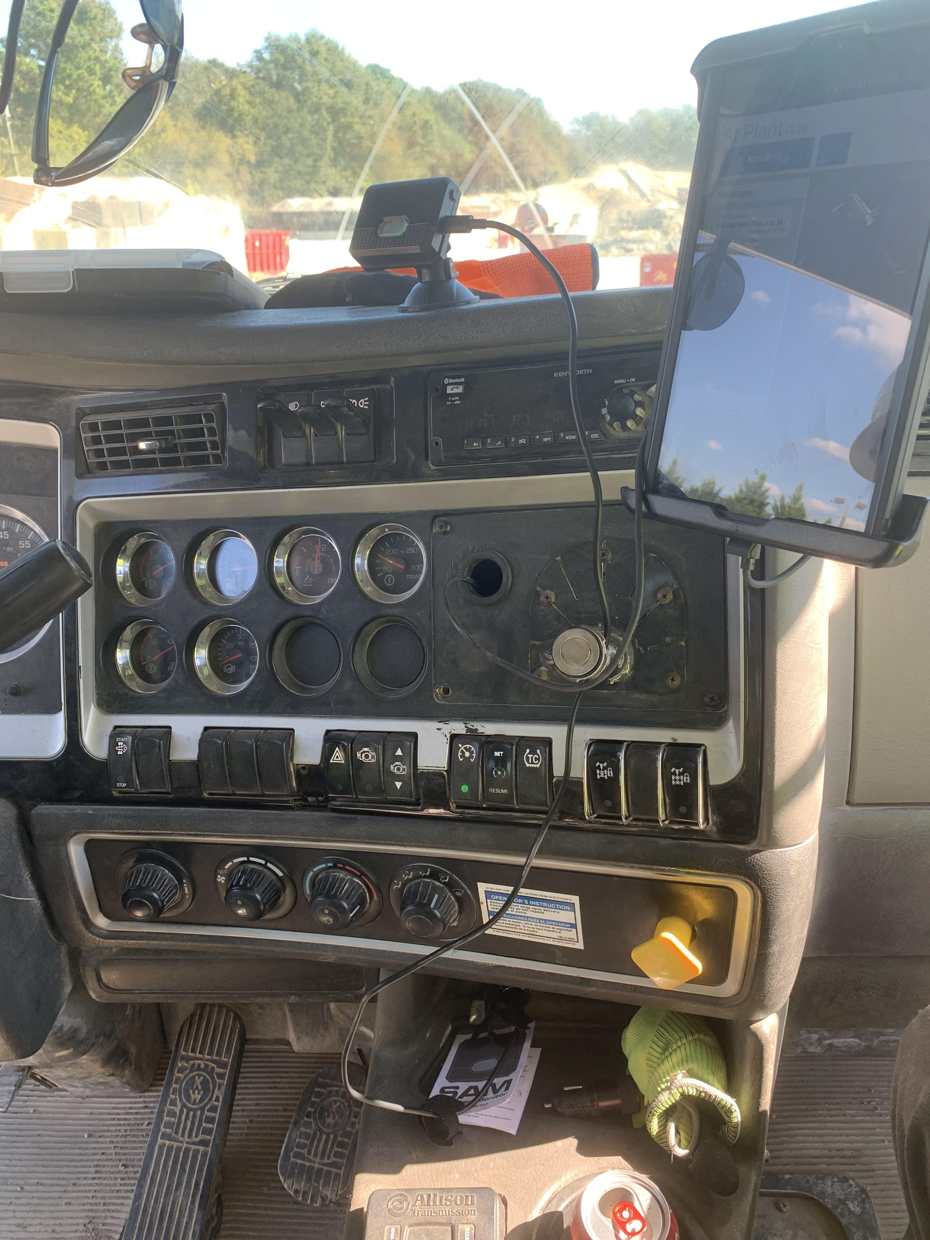
Final Design: Below shows the final alarm unit installed in the truck during user testing.
CNC Production of Client's Sensor Housing Design (Deliverable 1.2)
Below are the CNC tool paths for the top and bottom of the sensor made using Fusion 360 CAM software. The bottom of the sensor (middle and right image) involved using a jig for consistent flipping of the part to machine it on both sides.
The assembly of the CNC'd sensor unit with the clients electronic components
Branded User Manual (Deliverable 1.3)
The client had done no development on the brand and the target product visual identity prior to hiring me, as they were still in the prototype validation phase, but they informed me that they were envisioning the brand to sell a whole line of industrial tools and sensors. As their flagship product it was important to the client that the branding allowed the products to resonate with the target user: a blue collar laborer.
We discussed that it was important that the branding was very straightforward, but we also wanted to make the branding feel clean and considered, because the workers in that industry are critically important and deserve well designed tools to work with.
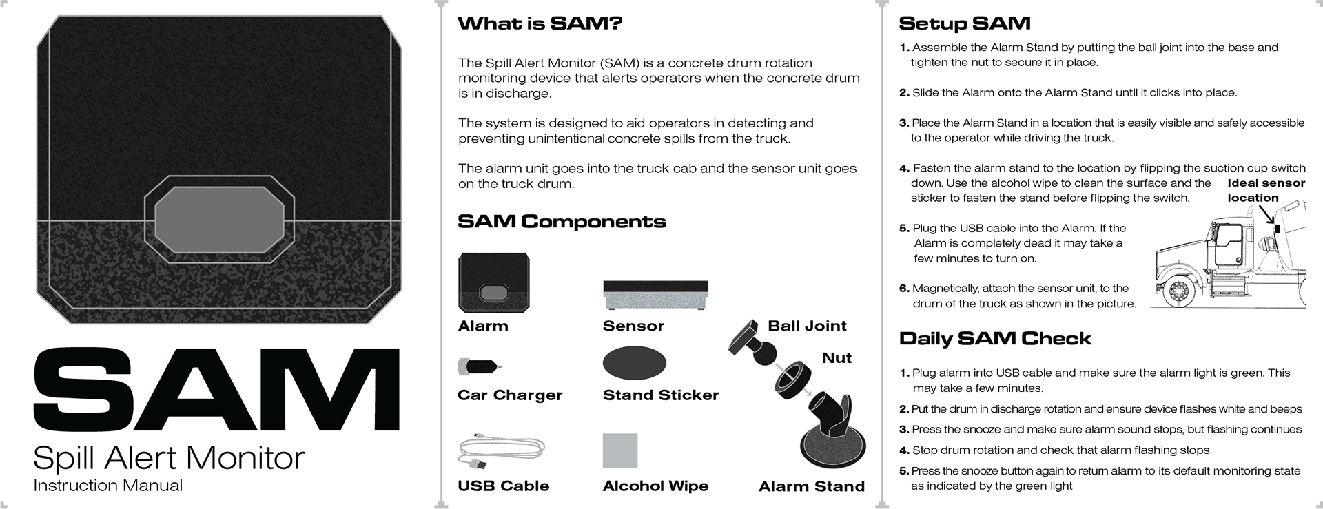
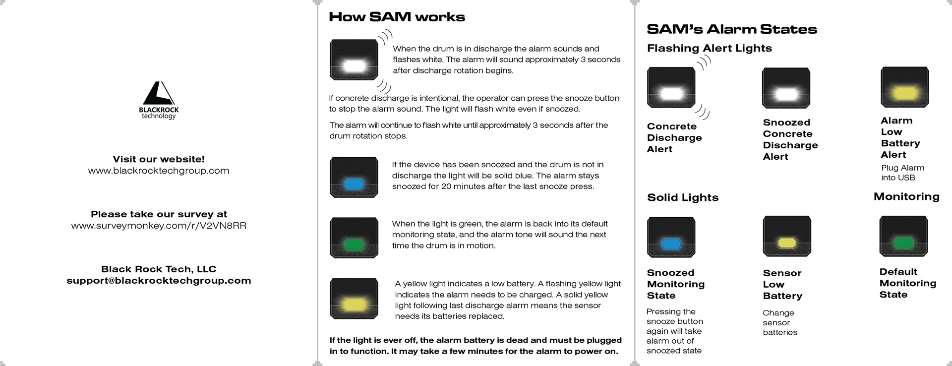
For the user manual, I targeted a very simplistic and diagrammatic approach to displaying the components of the concrete alarm system. Additionally, I created an acronym for the name of the sensor system, both to make it less of a mouthful to say, but to also make the system feel like a member of the team that the concrete truck driver can rely on: SAM.
Final Design: The final manual is designed to be printed on double side paper and folded into a trifold, so that it can both fit in the box but also conveniently stay in the concrete cab for user reference.
Custom Packaging (Deliverable 1.4)
The client wanted the custom packaging to be able to utilize a stock of 5x5 cardboard boxes that they had remaining from another project. I created custom cardboard inserts that secured all of the sensor system and the items needed to install it. The short run prototypes were ideated on and drafted by hand, then cleaned up and turned into vector art in Adobe illustrator and cut using a Cricut Maker.
The video below shows the final packaging being filled and unboxed as well as the user manual and setup of the alarm housing on the dashboard stand.
Onsite Installation:
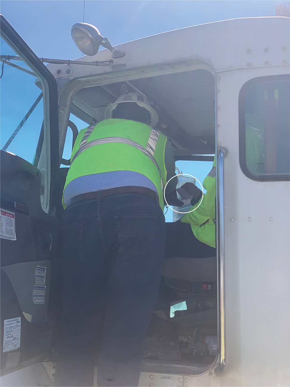
The customer was very excited about unboxing the product and informed us that the device looked "really cool". Once unboxing they properly installed the sensor unit onto the drum in under 30 seconds.

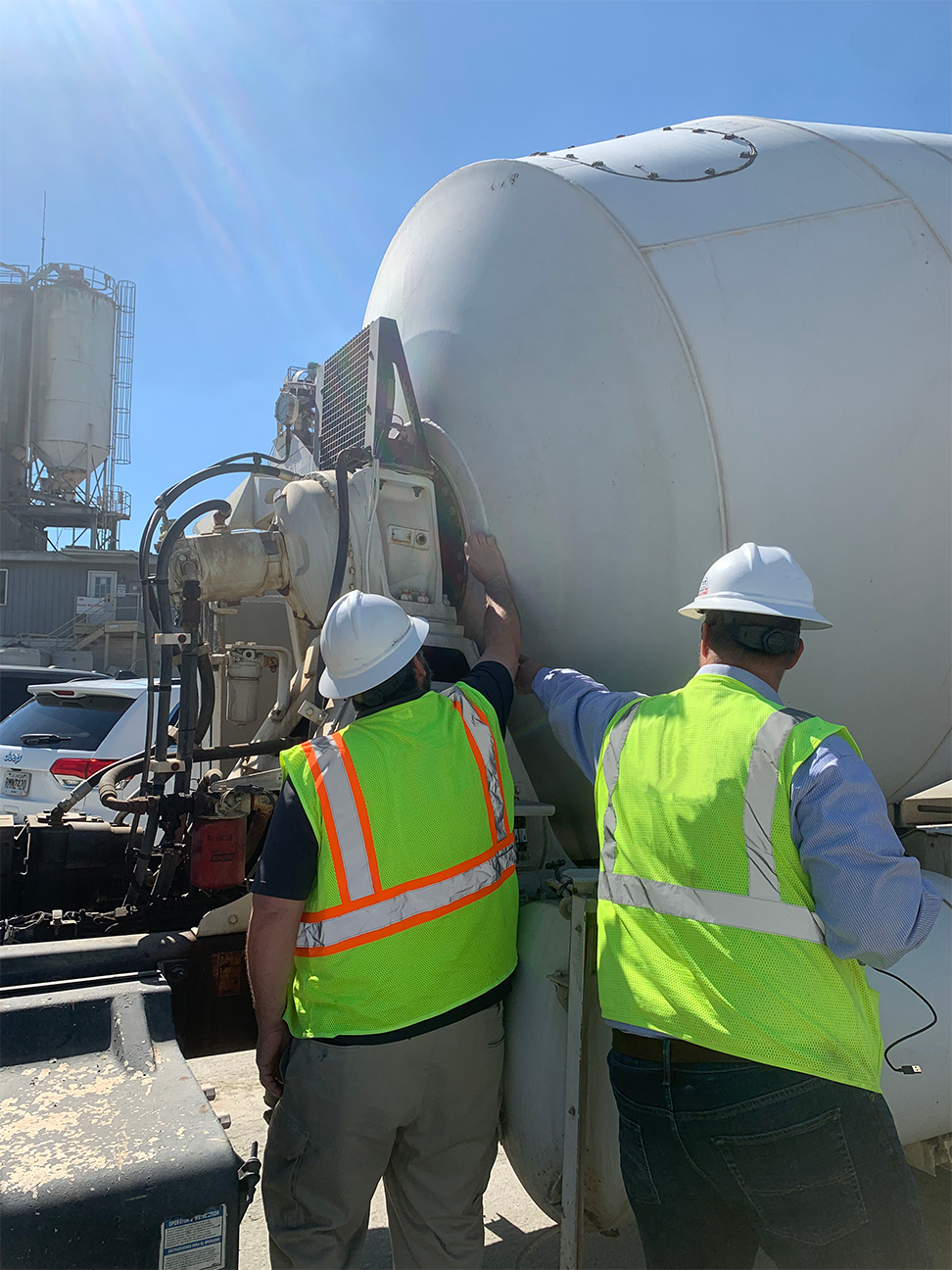
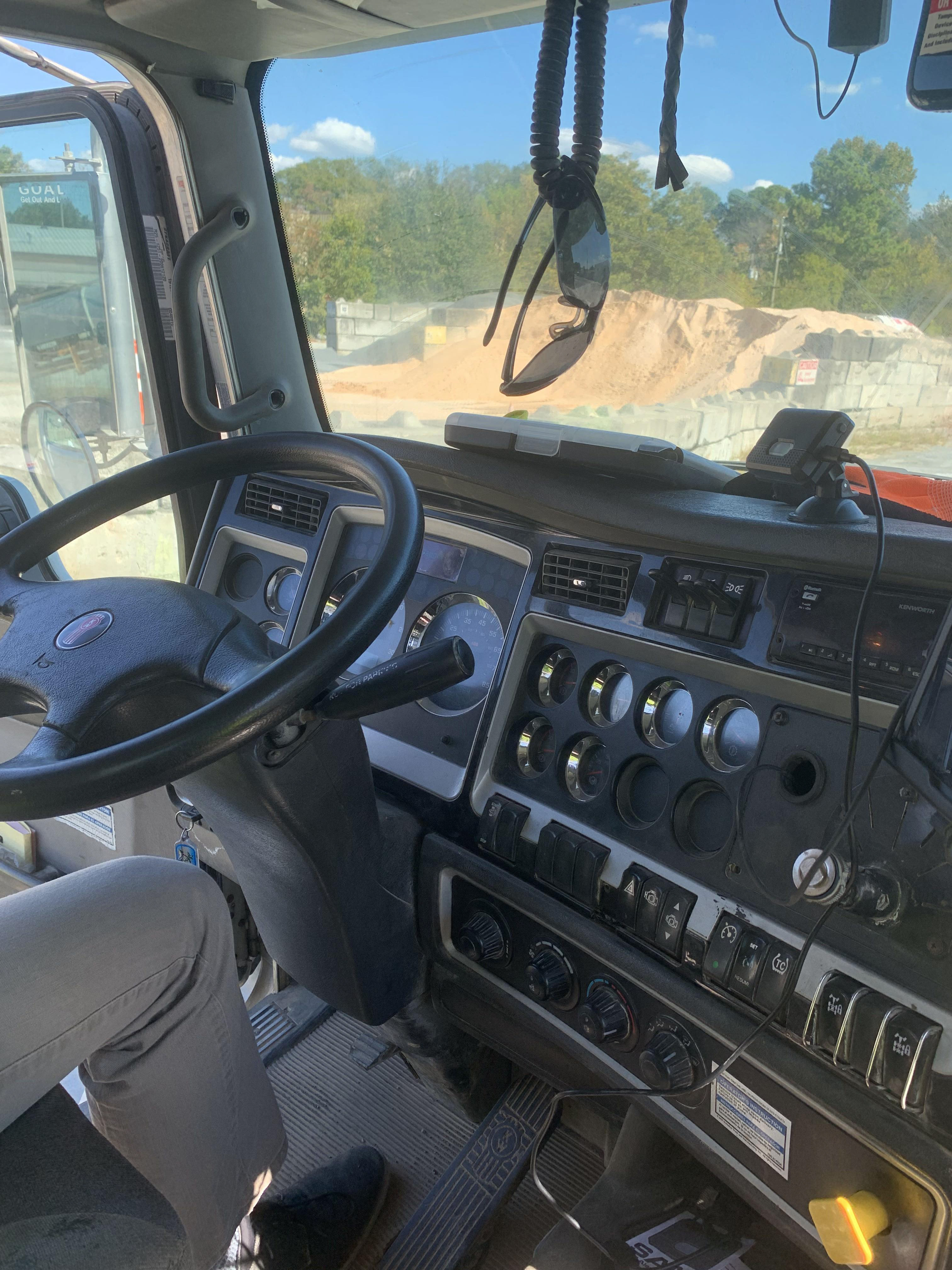
Following placing the sensor, the client and I observed the customer using the user manual to set up the SAM alarm unit inside the cab. (Circled in white in the first image below). They were able to properly install the device in under two minutes without any interference from the client or myself.
Phase 2:
Following the first 3 month user test period, the client received their sensors back from the customer and hired me to build a more robust and water tight sensor housing. Additionally, following the sensor redesign they wanted drawings created for all the alarm unit parts that I created, the new sensor housing exploded drawing, and the final customer deliverable which involved the designing of a part numbering system which they could eventually use for their entire company.
Deliverable 2.1: Redesign the sensor housing to be more water resistant, robust, and withstand the cleaning chemicals used on the concrete truck, including designing a testing procedure to ensure limited water ingress.
Deliverable 2.2: Create a part numbering system that the company can use for any products that it sells or will sell in the future
Deliverable 2.3: Deliver the engineering/assembly drawings for the sensor unit, alarm unit, and final customer deliverable.
Sensor Housing Redesign (Deliverable 2.1)
Following the 3 month user testing the client received the sensors back from the customer. Upon inspection it became apparent that the sensor housing was not robust enough for operation on the exterior of the truck for an extended period of time.
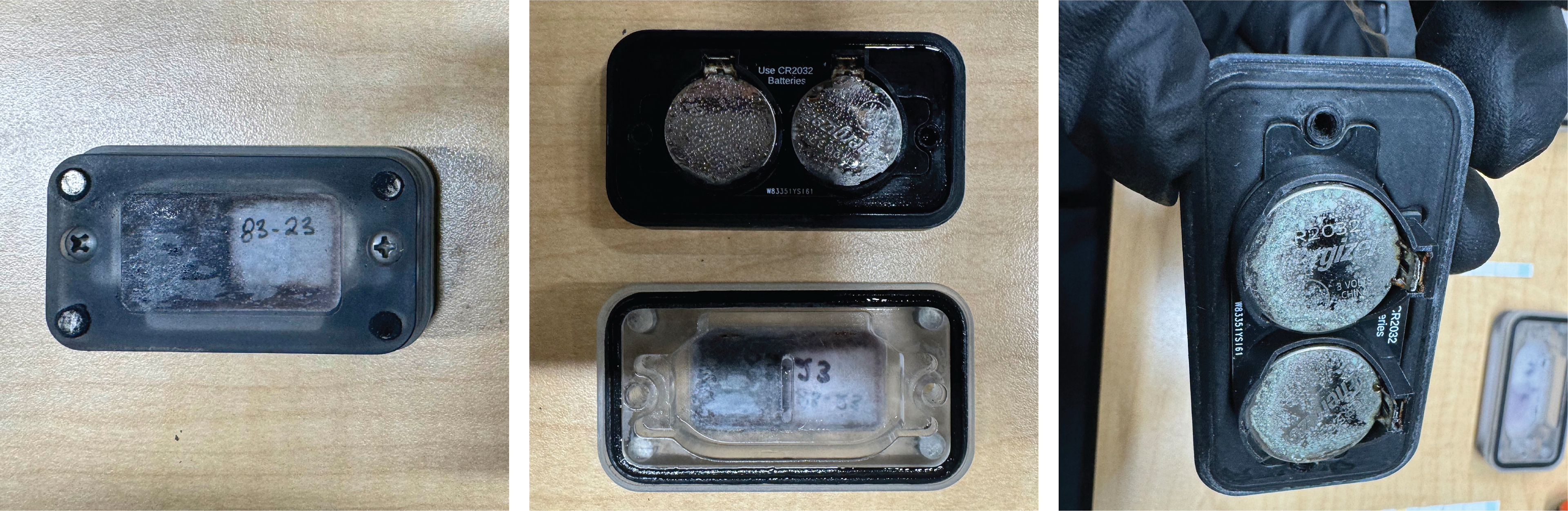
The new sensor needed to be changed in a few ways.
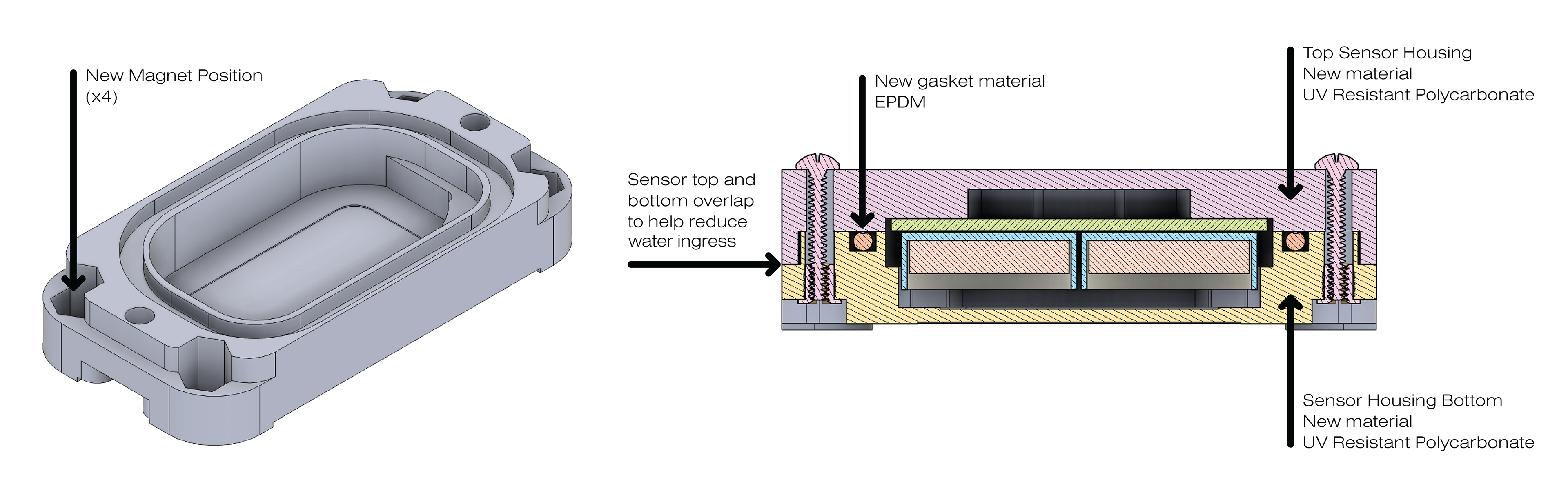
1) The magnets needed to be placed inside the housing to prevent the buildup of gunk and debris in the magnet pockets, which reduced the gripping strength of the magnets on the truck.
2) The housing needed to more effectively seal, so the force of the cleaning hoses that are used to wash the trucks cannot force water into the housing.
3) Select new materials used for the seal and housing need to be resistant to the phosphoric acid used in the cleaning solution that the company uses to ensure that the housing does not degrade over time.
Final Design: The final housing unit was modified to have the bottom of the sensor fit into the top of the housing, magnets press into the bottom of the housing on the inside of the housing, and new materials for the gasket and housing.
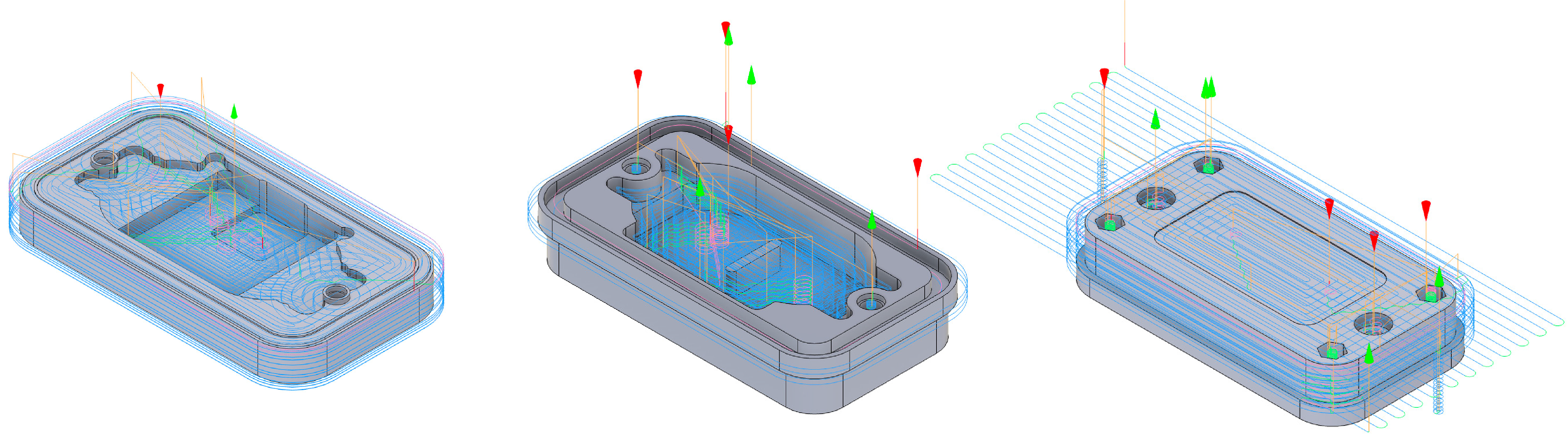
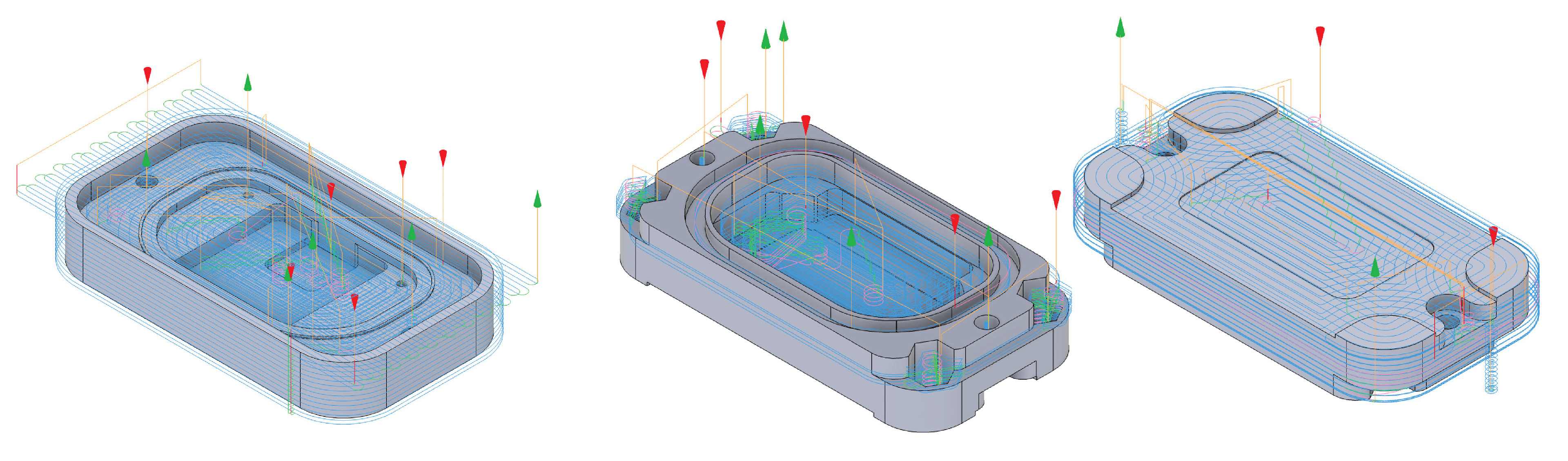
CNC tool paths for new sensor housing design. The sensor housing top could still be done by only machining one side as shown on the left and the sensor bottom was made by machining both sides as shown in the middle and right pictures.
After water testing the new housing under a hose with a flow rate of 50 liters per minute for a time period of two minutes directly on the seams of the housing there was still evidence of a small amount of water entering the housing. A color changing medium (from yellow to red) was used to indicate if water had entered the internal compartment of the housing during the test. Any other water shown on the inside of the gasket occurred from the opening of the housing following the test and does not indicate water leakage.
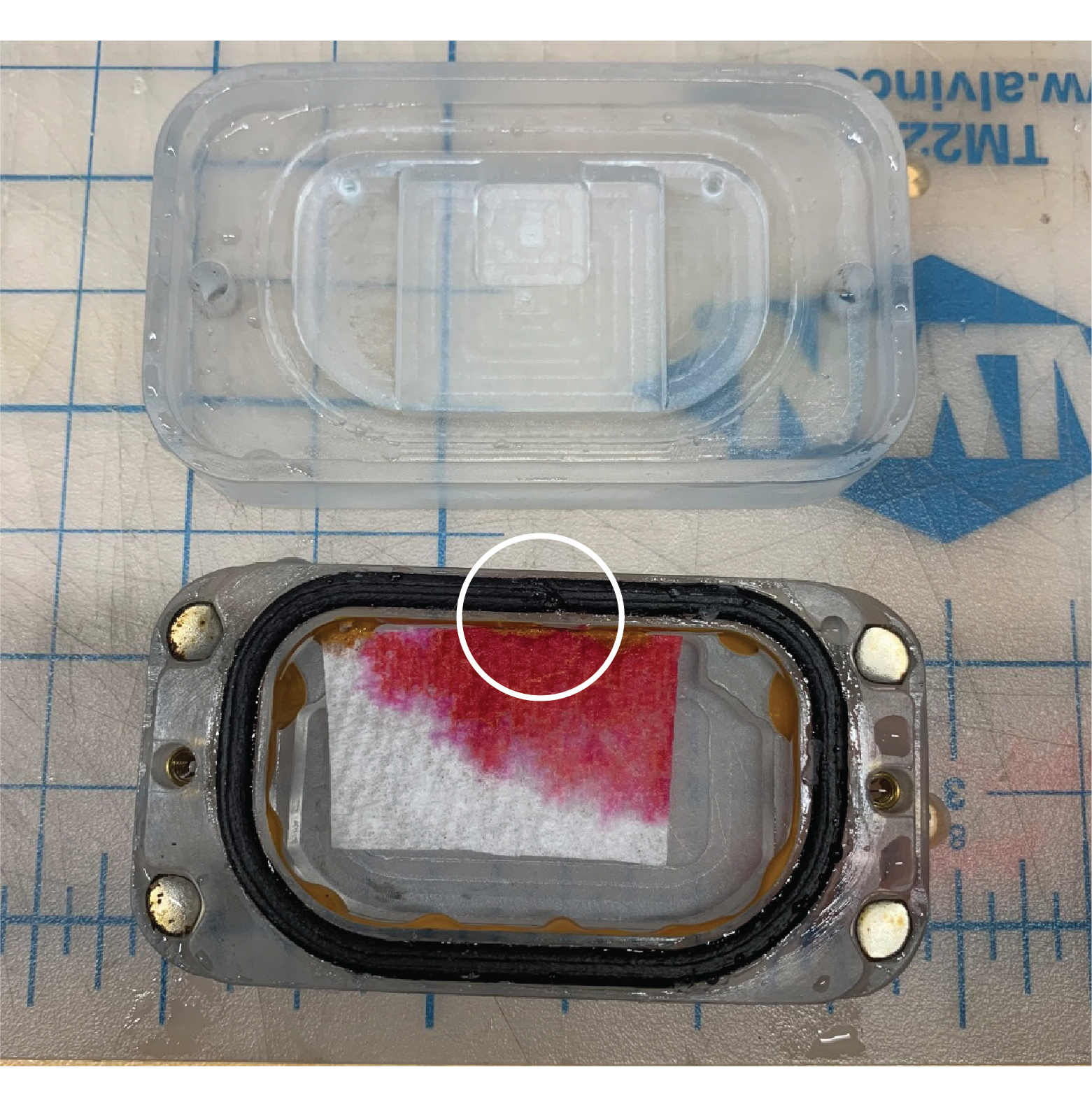
The red color change was localized around where the seam of the gasket was in the housing (circled in white). This was a prototyping artifact and was fixed by adjusting the gasket assembly method. Also, this test was likely the worst case scenario for treatment of the housing, because the hose used to clean the truck would likely not be sprayed on the housing for more than a few seconds and most of the water coming into contact with the sensor would be running water off the truck or rain. To ensure maximum water ingress protection the newly assembled seal was added to the housing, and as an extra sealing precaution silicone caulking was used to adhere the gasket into the gasket groove in the housing. No water entered the housing during the second water ingress test.
Part Numbering System (Deliverable 2.2)
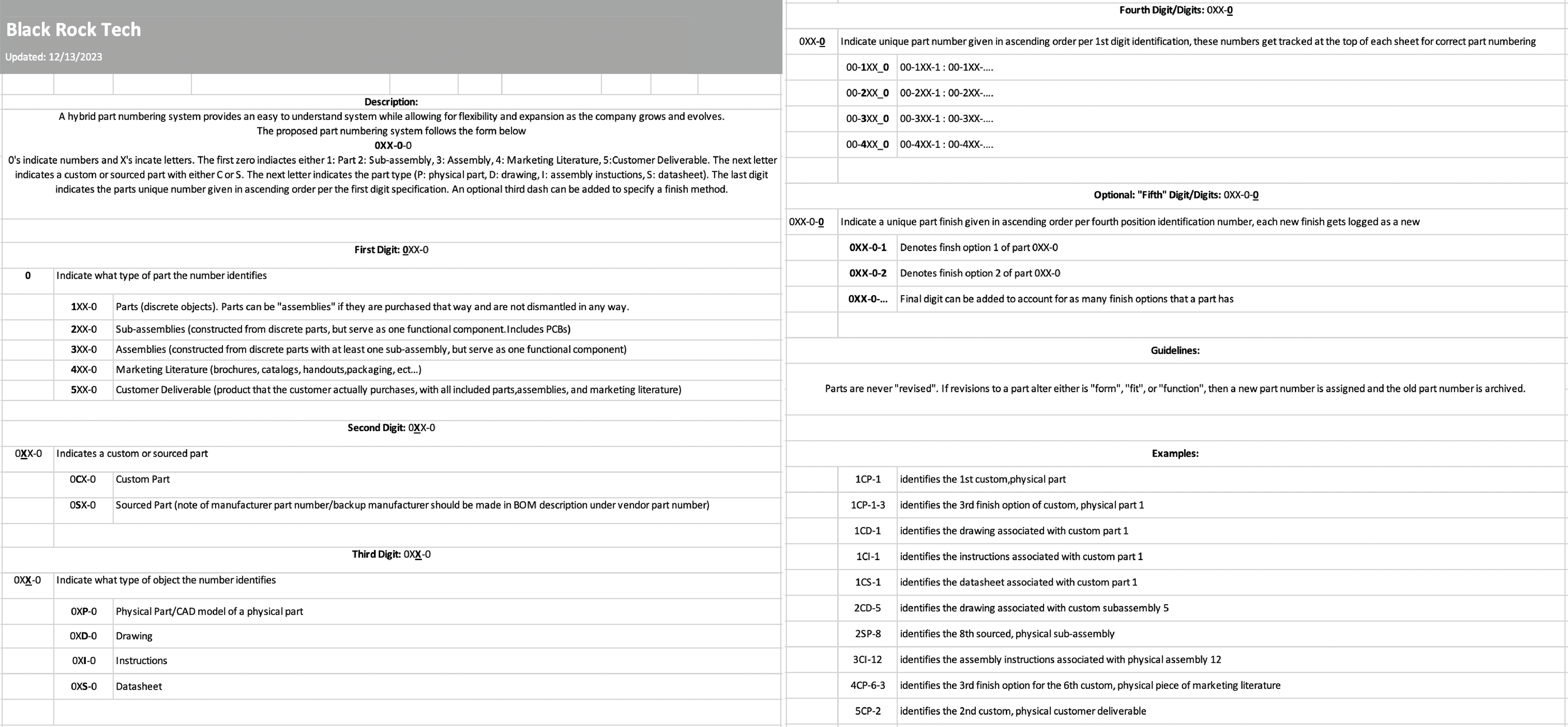
The part numbering system designed for the client is detailed in the excel spreadsheet below. Examples of how parts would be identified can be seen in the second column.
Engineering Drawings (Deliverable 2.3)
Below are the exploded and detailed part drawings for the sensor unit housing, alarm unit, and the final customer deliverable. (Click to change through the different drawings)
View the product on the Blackrock Technology website Below!